Since the introduction of Liquid Silicone Rubber (LSR) in the 1970’s, the optimization of processes and procedures has become increasingly important for achieving higher strength, hardness, flexibility, soft-feel, and durability properties in the end product; reducing lead times and costs.
During the LSR production process, a crosslinking reaction occurs as the liquid silicone rubber flows through the extruder, injection mold, or compression mold. Determining the key parameters in processing is an important first step, as these parameters directly affect the crosslinking reaction [1]. Less than optimum processing parameters can lead to air voids, warpage, swelling, incomplete filling, premature gelation, incorrect curing profile, local overheating, cracks and deformations. When LSR was first introduced, any processing and part quality issues that occurred could only be addressed during production, after the mold was complete, and resulted in significant monetary losses.
Today, the technology exists and tools are available that can simulate and evaluate numerous design and processing conditions, before the mold is built or production begins. There are a variety of systems that can help detect and alleviate many of these issues, some that focus on part production, and others that focus on mold design. Companies such as SIMTEC Silicone Parts, a recognized technologically-advanced LSR injection molder, and other molders have taken advantage of the technology, and utilize CAD, CAM and/or CAE programs to give them the ability to foresee potential production issues, and make the appropriate adjustments before building tools, or initiation of the Liquid Silicone Rubber Injection Molding Production. The end customer benefits as well, with the reduction of their product development costs, and improved end-product quality.
COMPUTER AIDED DESIGN, MANUFACTURING AND ENGINEERING (CAD/CAM/CAE)
Computer Aided Design (CAD) systems incorporate the 2D data from the engineering drawing of the part/product design, and creates 3D data for production of the mold and parts. In addition, any modifications or revisions made to the 3D structure will automatically update the 2D drawing [2].
Ideally, a Computer Aided Manufacturing (CAM) system is used in conjunction with the CAD system. A CAM system utilizes the 3D CAD data for production of the mold/die used in the injection molding or extrusion of Liquid Silicone Rubber parts. The data is translated into language a machine understands, creating the tool cutting paths used to manufacture the molds/dies − this is known as Numerical Control (NC) [2] automation. In some cases, a part design may need to be modified to improve mold manufacturing, or required due to elaborate features in the part design, difficulty producing certain mold surfaces, or the availability of tools. Because of the ever-present possibility a change in the part design can occur, it is important that CAD and CAM systems are compatible to allow for real-time updates and feedback.
Once the CAD/CAM information has been generated a Computer Aided Engineering (CAE) system can be used to simulate the process. CAE systems analyze both the way the product is processed, and its performance. Please note, unlike other materials, when processing Liquid Silicone Rubber (LSR), a CAM analysis is necessary before proceeding with Computer Aided Engineering.
Using the CAD/CAM data, the CAE program simulates, validates and optimizes the process. This is a multi-step process outlined below, and is necessary for attaining the desired optimized processing and parts production:
- Pre-processing: The variables to be analyzed are introduced
- Analysis: Silicone rubber processing is simulated
- Post-processing: The results are visualized using diagrams, charts, figures and/or videos
A CAE system can assist in an optimal mold design, optimum processing parameters taking into consideration the material and product, and calculates the mold filling behavior, temperatures, pressures, weld lines, air bubbles, etc. Typically CAE systems are based on Finite Element Method (FEM). In addition, for Liquid Silicone Rubber (LSR), a model for analyzing the curing behavior is also used [3]. FEM converts the process into Partial Differential Equations (PDEs) that are related using numerical model equations, and solved using numerical methods–all done in the software’s backend. A final graphic is produced providing a maximum amount of information, directly correlated to the CAD data, and in accordance with the variables introduced in pre-processing. The value of these simulations are the time and costs savings achieved by avoiding mold/die modifications after production and testing. [2]
SIMULATION OF THE LIQUID SILICONE RUBBER (LSR) PROCESSING
When using LSRs, additional processing analysis is necessary to determine the optimal parameters during mixing. Normally, processed LSR consists of a 2-part liquid silicone rubber, therefore the proportion, shutoff valve, and pressure must be controlled to avoid negative effects during processing [1]. The mixing simulation provides flow visualization, and offers a better understanding of the impact the process variables will have on the final product’s properties.
Since part and mold designs directly affect the temperature profile and curing behavior during processing, poorly implemented changes to sections, ribs, bosses, housings, and other factors can cause a reduction in the product’s mechanical properties due to higher shear stress resulting from increased temperature and faster curing than desired, and will lead to material degradation [4]. Since reprocessing liquid silicone rubber is still under developed, problems such as flashing, scorching or premature cure are challenges that should be evaluated before production [4]. Due to the associated quality issues, high precision, high quality molders like SIMTEC do not use reprocessed LSR’s. Knowledge of a material’s characteristics and the product design will also increase productivity, decrease nonconformities, and improve the quality of the final product.
“Before the construction of a mold for processing Liquid Silicone Rubber (LSR),
consideration should be given to which parameters and conditions are best in order to achieve the highest properties in the part based the application.”
Other design parameters that affect processing can also be evaluated during the simulation. One of the most critical parameters in the injection molding process is the location of the gate, this is the place in the mold where the Liquid Silicone Rubber (LSR) enters into the mold cavity. Placing the gate in the wrong location can negatively affect the quality of the final product. Polymer design guidelines suggest the gate should not be located in areas where high external pressures are applied. The gate is considered a weak spot in the part, therefore it is advised that the gate should be as small as possible, and should not be placed on technical surfaces or those with critical dimensions. Sometimes the effect of gate location is not obvious, but with simulation it is possible to see the effect the location will have on the filling, cure, final dimensions, surface quality, shrinkage and final properties of the silicone rubber product, as well as calculate shear stress, air traps, weld lines, and viscosity, before a single gram of material is used.
A common strategy used to determine the optimal gate location is to run three different simulations [2]. In the first simulation, the gate is located centrally along the part; in the second simulation the gate is moved 90° around the part to the smallest side of the part; and for the third simulation, the gate is located on the bottom of the part. The simulation with fewest weld lines, better flow behavior, and lower cycle time are chosen.
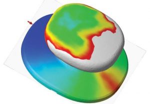
Figure 1. Effect of gate location [4]
It is well known that premature curing should always be avoided. During a process simulation, the filling speed (slow speed, premature curing) and the flow length can be calculated. The effects the temperature of the material, the mold, and the part thickness has on the curing can also be forecast.
Some computational tools currently have the ability to anticipate or simulate changes in inherent properties of the material through the PVTC (Pressure, specific Volume, Temperature, and Cure) diagram. The effect of swelling and changes in the coefficient of thermal expansion can also be used to calculate the contraction and possible warpage.
The information obtained using different process conditions and understanding their effect, makes it possible to calculate an optimum processing time. For certain processing conditions, how the temperature and cure profiles change, and how the processing defects appear or disappear can be shown. By conducting a series of simulations, optimum processing conditions can be obtained. With elastomers, if the curing time is long, the costs will be higher and profit margins lower [1]. As discussed, there are many advantages to using simulations, and there are also areas for improvement. Currently a database does not exist with all of the various compounds that are available, therefore it can be cumbersome to sort through the thousands of possible combinations of additives that can be used in a specific application [3].
Having the capability to simulate the processing of Liquid Silicone Rubber (LSR) is beneficial to both customers and processors. Processors are aided with having a visualization of changes in the final product based on variations in the processing conditions, design processing validation, and optimization. As a result customers enjoy less time and costs due to the reduced need for prototypes, remanufacturing and reprocessing, and expedites product development time and time-to-market.
Contact SIMTEC Silicone Parts and take advantage of the benefits our optimized manufacturing, and our team of experts in LSR and LSR Multi-Shot injection molding solutions can offer you on your next project. Contact Us today!
References
- mddionline.com
- Dangel. Mould design for beginners. Carl Hanser Verlag, 2016.
- moldmakingtechnology.com
- moldex3D.com